Introduction
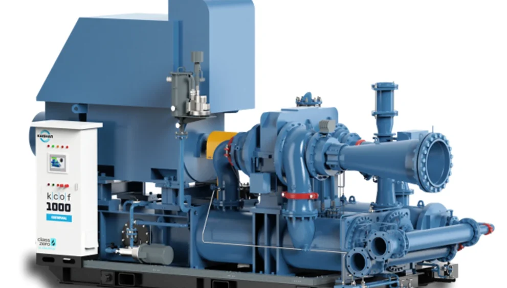
Centrifugal air compressors are the backbone of many large vessels, especially those requiring significant volumes of compressed air for process control, cargo operations, and automation. Relying on rotational energy and dynamic compression rather than positive displacement, these machines deliver reliability and efficiency with fewer moving parts than classic reciprocating designs.
Technical Characteristics
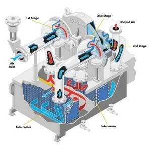
- Principle: Air enters axially and is accelerated radially by high-speed impellers. The kinetic energy imparted to the air is converted to pressure in stationary diffusers, and finally collected in the volute.
- Pressure Range: Multi-stage units can deliver up to 205 bar, while 2-3 stage setups typically reach 13 bar.
- Cooling: Primarily water-cooled, with compact, high-efficiency tube bundle heat exchangers for both inter- and after-cooling.
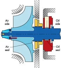
- Lubrication: Oil-free operation is increasingly common, using non-contact labyrinth seals and advanced bearing designs.
- Automation: Features such as inlet guide vanes, real-time monitoring, and advanced control interfaces are now standard.
Working Principle
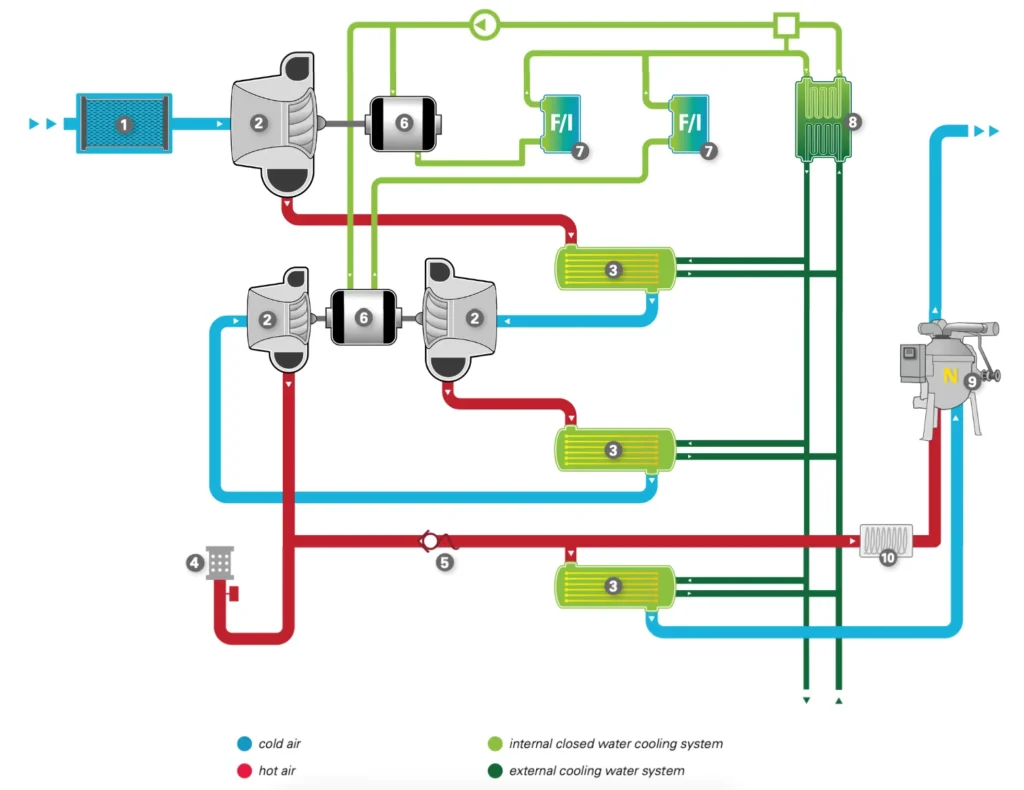
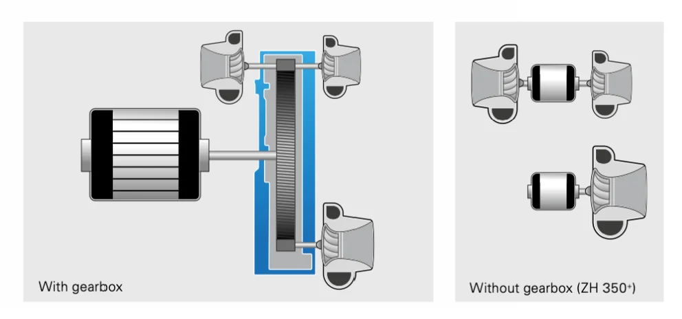
The air enters the via the air filter (1) and then proceeds through three stages of compression (2) . After each stage, an inter- or aftercooler (3) cools down the hot air. After the third stage of compression blow-off (4) takes place before the check valve (5) and aftercooler to rapidly de-pressurize the compressor’s internal air volume during unload transitions. The three stages of compression are driven by two high-speed motors (6) without a gearbox. The motors and frequency inverters (7) are cooled in two parallel streams by an internal closed water cooling system, which is independent of cooling water quality supplied externally. The cooling water is also distributed among the internal heat exchanger (8) . It features a constant water temperature. Optional components include Atlas Copco’s ND heat-of-compression rotary drum dryer (9), and pre-heating of part of the hot air (10) after the third stage if required.
Case Study: Diagnosing a Sudden Drop in Air Delivery
On a large RoRo vessel, a newly appointed 3rd Engineer noticed the centrifugal compressor could not maintain pressure above 6 bar during a cargo run. After initial panic, the team inspected the air filter inlet—discovered salt spray and soot accumulation, severely restricting intake. Cleaning and replacing the filter restored normal operation, highlighting the importance of environmental protection and routine checks in harsh marine conditions
Practical Running Condition Assessment
- Monitor suction and discharge pressures: Sudden drops may highlight internal air leaks or inlet choking.
- Listen for changes: A healthy centrifugal compressor on a ship should run quietly with only a gentle hum. Unusual resonance or grinding points to bearing or impeller issues.
- Temperature checks: Overheated coolers or inconsistent discharge temperatures can predict fouling, saltwater ingress, or failed bearings.
Inspect vibration logs: Install portable vibration meters and investigate any upward trends quickly
Maintenance Difficulties
- Impeller and Housing Access: The precision alignment of impellers means any disassembly must be performed with utmost care. Shaft or bearing misalignments can rapidly escalate damage.
- Corrosion Risks: Salt-laden air is a constant threat; routine dehumidification and regular inspection for pitting/corrosion are essential.
Instrumentation Sensitivity: Control systems, guide vanes, and feedback mechanisms are sensitive to dust and humidity—demanding frequent calibration and protective measures.